Diagram for WPF has some built-in, automatic layouts to arrange nodes based on their relationships. Currently, we have three standard layouts hierarchical tree layout, radial tree layout, and organizational layout. If these layouts are not enough, you can use any other third-party or open-source layout engine for arrangements and you can use diagram’s visualization and other cool features. Microsoft Automatic Graph Layout (MSAGL) has advanced layouts in its layout engine. In this blog, we’ll see how to use this layout engine and visualize a layout using Syncfusion’s diagram control. Following are some sample graphs rendered using the MSAGL layout engine.
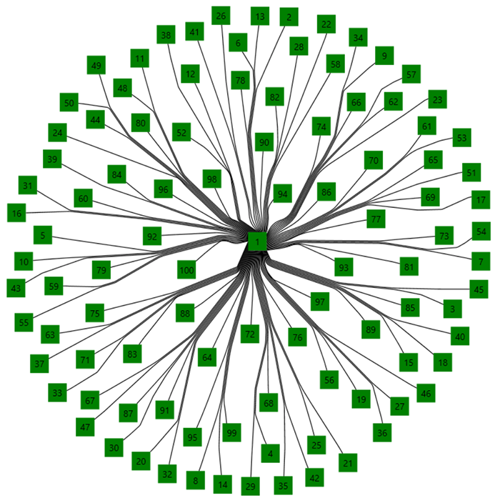
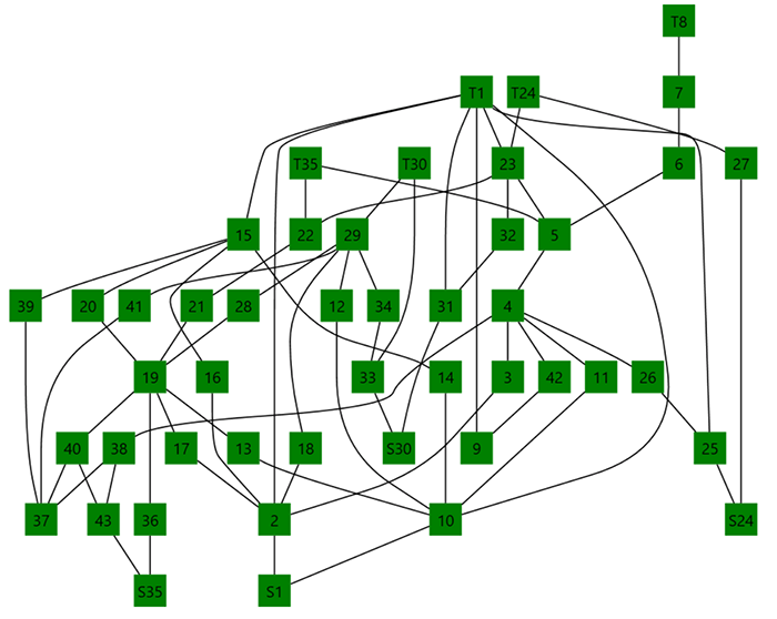
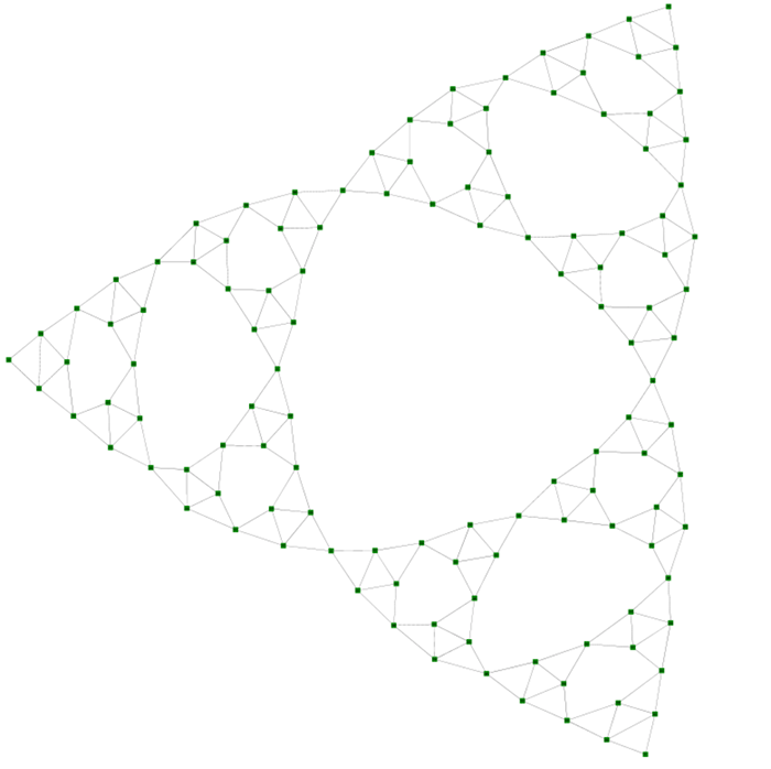
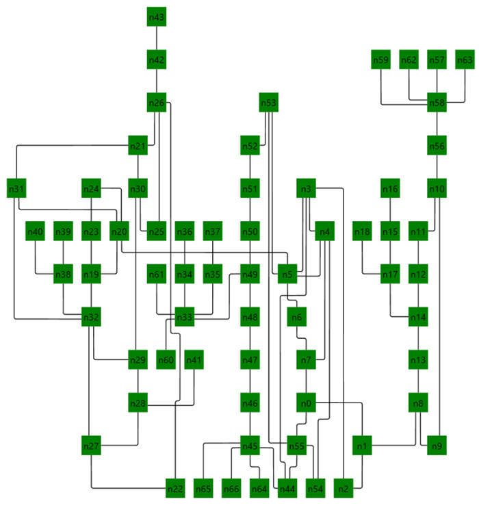

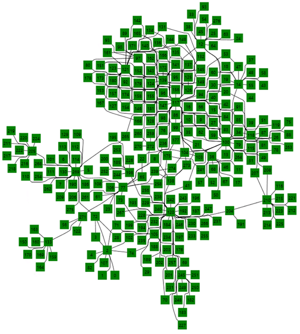
Now let’s see the step-by-step process on how to visualize the graph layout and line routing from the MSAGL layout engine into diagram.
Load or prepare a diagram for diagram model
If you are new to diagram, please go through the following topics to understand what diagram is and how to build it using nodes and connectors:
Convert model from diagram to MSAGL
// Convert model of SfDiagram to MSAGL.
public static GeometryGraph ToMSAGLGraph(this IGraph sfDiagramModel)
{
    // Create a graph.
    GeometryGraph MSAGLmodel = new GeometryGraph();

    foreach (var node in (sfDiagramModel.Nodes as IEnumerable<INode>))
    {
        // Create MSAGL node.
        Microsoft.Msagl.Core.Layout.Node msaglNode = new Microsoft.Msagl.Core.Layout.Node(

            CurveFactory.CreateRectangle(

                // Specify size of a node.
                node.UnitWidth,
                node.UnitHeight,

                // Specify empty position, as layout will take care of positioning.
                new Microsoft.Msagl.Core.Geometry.Point()),

            // Give reference to diagram node.
            node);

        // Add node into MSAGL model.
        MSAGLmodel.Nodes.Add(msaglNode);
    }

    foreach (var con in sfDiagramModel.Connectors as IEnumerable<IConnector>)
    {
        // Create MSAGL connector.
        MSAGLmodel.Edges.Add(
            new Edge(
                // Set source and target by finding MSAGL node based on SfDiagram node.
                MSAGLmodel.FindNodeByUserData(con.SourceNode),
                MSAGLmodel.FindNodeByUserData(con.TargetNode))
            {
                Weight = 1,
                UserData = con
            });
    }
    return MSAGLmodel;
}- RankingLayoutSettings: Layout to arrange graph in a tree structure. It will also rearrange in such a way that it minimizes the sum of edge length and edges crossing over each other.
- MdsLayoutSettings: Multidimensional scaling layout algorithm.
- FastIncrementalLayoutSettings: Fast incremental layout is a force-directed layout strategy with approximate computation of long-range node-node repulsive forces to achieve O(n log n) running time per iteration.
- SugiyamaLayoutSettings: Layout to arrange a tree-like structure.
Configure routing technique
- Spline: Routing is done using curved segments such as Bezier and Arc segments.
- SplineBundling: This is also a spline routing. Additionally, it will group similar connections close to each other.
- StraightLine: Just a straight line connecting the source to target.
- SugiyamaSplines: A spline curve more suitable for Sugiyama layout.
- Rectilinear: Orthogonal or perpendicular segments to connect the nodes.
- RectilinearToCenter: A rectilinear routing but connecting toward the center of a node.
Run MSAGL layout and routing
LayoutHelpers.CalculateLayout(graph, settings, null);Convert model from MSAGL back to diagram
// Sync SfDiagram model based on MSAGL model.
public static void UpdateSfDiagram(this IGraph diagram, GeometryGraph graph)
{
    // Move model to positive axis.
    graph.UpdateBoundingBox();
    graph.Translate(new Microsoft.Msagl.Core.Geometry.Point(-graph.Left, -graph.Bottom));

    // Update node position.
    foreach (var node in graph.Nodes)
    {
        (node.UserData as INode).OffsetX = node.BoundingBox.Center.X;
        (node.UserData as INode).OffsetY = node.BoundingBox.Center.Y;
    }

    // Update connector segments based on routing.
    foreach (var edge in graph.Edges)
    {
        IConnector connector = edge.UserData as IConnector;
        connector.Segments = new ObservableCollection<IConnectorSegment>();
        SyncSegments(connector, edge);
    }
}

// Sync segments of connector.
private static void SyncSegments(IConnector connector, Edge edge)
{
    var segments = connector.Segments as ICollection<IConnectorSegment>;

    // When curve is a line segment.
    if (edge.Curve is LineSegment)
    {
        var line = edge.Curve as LineSegment;
        connector.SourcePoint = new Point(line.Start.X, line.Start.Y);
        segments.Add(new StraightSegment
        {
            Point = new Point(line.Start.X, line.Start.Y)
        });
        segments.Add(new StraightSegment
        {
            Point = new Point(line.End.X, line.End.Y)
        });
    }

    // When curve is a complex segment.
    else if (edge.Curve is Curve)
    {
        Point? pt = null;
        foreach (var segment in (edge.Curve as Curve).Segments)
        {
            // When curve contains a line segment.
            if (segment is LineSegment)
            {
                var line = segment as LineSegment;
                if (pt == null)
                {
                    pt = new Point(line.Start.X, line.Start.Y);
                    segments.Add(new StraightSegment
                    {
                        Point = pt
                    });
                }
                segments.Add(new StraightSegment
                {
                    Point = new Point(line.End.X, line.End.Y)
                });
            }

            // When curve contains a cubic Bezier segment.
            else if (segment is CubicBezierSegment)
            {
                var bezier = segment as CubicBezierSegment;
                pt = new Point(bezier.B(0).X, bezier.B(0).Y);
                if (pt == null)
                {
                    segments.Add(new StraightSegment
                    {
                        Point = pt
                    });
                }
                segments.Add(new CubicCurveSegment
                {
                    Point1 = new Point(bezier.B(1).X, bezier.B(1).Y),
                    Point2 = new Point(bezier.B(2).X, bezier.B(2).Y),
                    Point3 = new Point(bezier.B(3).X, bezier.B(3).Y),
                });
            }

            // When curve contains an arc.
            else if (segment is Ellipse)
            {
                var ellipse = segment as Ellipse;
                var interval = (ellipse.ParEnd - ellipse.ParStart) / 5.0;
                for (var i = ellipse.ParStart;
                            i < ellipse.ParEnd;
                            i += interval)
                {
                    var p = ellipse.Center
                        + (Math.Cos(i) * ellipse.AxisA)
                        + (Math.Sin(i) * ellipse.AxisB);
                    segments.Add(new StraightSegment
                    {
                        Point = new Point(p.X, p.Y)
                    });
                }
            }
            else
            {

            }
        }
        segments.Add(new StraightSegment());
    }
    else
    {

    }
}Summary
If you like this blog post, we think you’ll also like the following free e-books:
WPF Succinctly
WPF Debugging and Performance Succinctly
C# Succinctly
Be the first to get updates
Stay Ahead – Get Exclusive Updates First!
Meet the Author
Jegan RJegan R is a Product Manager in Syncfusion. He is good in WPF control development. He worked for Diagram component and currently working for Tools Components.


Comments (2)
Hi,
please it is possible to setup MSAGL Edges corners to 90° degrees:
This is my setup:
GeometryGraph graph = new GeometryGraph();
graph.Nodes!.Add(new Node(CurveFactory.CreateRectangle(80, 60, new Point(100, 100)), null));
graph.Nodes!.Add(new Node(CurveFactory.CreateRectangle(80, 60, new Point(94, 80)), null));
graph.Edges!.Add(new Edge(graph.Nodes[0], graph.Nodes[1]) {
Weight = 1,
UserData = null
});
graph.UpdateBoundingBox();
graph.Translate(new Point(-graph.Left, -graph.Bottom));
This is my result still without 90° corners:
https://i.stack.imgur.com/jhWBa.png
Thanks.
Hi Lukas,
We have modified the sample, based on your requirement for the edges of the Connector in 90 degrees. From the MSAGL Layout, we get the curve of the edge(Connectors) with many types like LineSegment, CubicBezierSegment, and Ellipse then we converted those edges into our SfDiagram connector segments using their points to achieve your requirement. Please find the modified sample for your requirement in the below link.
Link: https://github.com/SyncfusionExamples/WPF-Diagram-Examples/tree/master/Samples/Automatic%20Layout/Custom%20Layout/wpf-diagram-custom-layout-master
Regards,
Sarath