TL;DR: Discover how to use the React Diagram Library to create interactive UML class diagrams, enhancing software modeling through easy and dynamic diagramming.
UML (Unified Modeling Language) Class Diagrams visually depict the static structure of an application and are extensively employed in modeling object-oriented systems. They hold a unique position in UML diagrams, as it directly aligns with object-oriented languages.
A class diagram shows the classes, attributes, operations, and the relationships between them. This helps software engineers in developing the code for an app. It is also used for describing, visualizing, and documenting different facets of a system. Here’s a brief overview of the key components:
- Class: Represents a blueprint for objects. It contains attributes (properties) and methods (functions or operations).
- Attributes: Characteristics of a class, represented as variables.
- Methods: Functions or operations that the class can perform.
- Relationships:
- Association: Represents a relationship between two classes.
- Inheritance: This shows that a class is derived from another class.
- Aggregation: Represents a whole-part relationship.
- Composition: A more potent form of aggregation indicating ownership.
- Dependency: A weaker relationship showing that a class depends on another class.
This article will explore how the Syncfusion React Diagram Library can be used to develop an interactive user interface for designing UML class diagrams.
Prerequisites
Before you begin, ensure the following software is installed on your computer.
- Node.js version 16.14.0
Creating a diagram surface
Let’s create a diagram surface by following these steps.
Step #1: Create a folder named UML Class Diagram.
Step #2: Create a new React app using the following command.
npx create-react-app my-diagram-appThen, replace the name my-diagram-app with your desired app name. For example, if you want to create an app named uml-class, use the following command.
npx create-react-app uml-classStep #3: Navigate to your app directory. Change your working directory to the newly created app by using the following command.
cd uml-classStep #4: Use the following command to start the development server and see your app in action.
npm startThis will open your app in your default web browser at http://localhost:3000/.
Step #5: Then, open the package.json file and add the following necessary package dependencies.
"dependencies": {
    "react": "18.1.0",
    "react-dom": "18.1.0",
    "@syncfusion/ej2-base": "27.2.2",
    "@syncfusion/ej2-react-base": "27.2.2",
    "@syncfusion/ej2-diagrams": "27.2.3",
    "@syncfusion/ej2-react-diagrams": "27.2.3"
  },
Step #6: Use the following command to install all dependent packages.
npm install
Step #7: Add the dependent scripts and style CDN reference links in the index.html file.
<head>
<meta charset="utf-8">
<title>React UML Class Diagram</title>
<base href="/">
<meta name="viewport" content="width=device-width, initial-scale=1">
<link rel="icon" type="image/x-icon" href="favicon.ico">
<script src="https://cdn.syncfusion.com/ej2/syncfusion-helper.js" type ="text/javascript"></script>
<link href="https://cdn.syncfusion.com/ej2/26.1.35/material.css" rel="stylesheet"/>
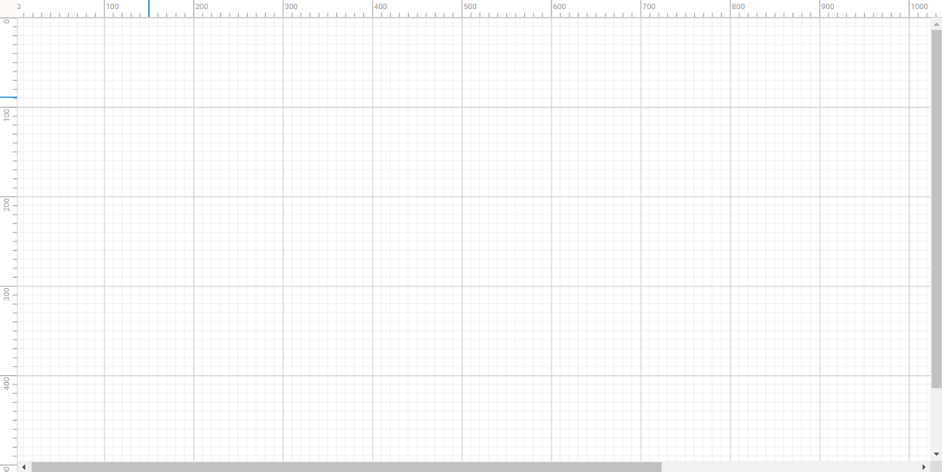
</head>Step #8: To include the React Diagram component in your app, import the DiagramComponent from the ej2-react-diagrams package. The required arguments, such as the width, height, and collection of nodes and connectors, must be included in the app.component.html file.
Refer to the following code example.
<div id="diagram-space" className="sb-mobile-diagram">
   <DiagramComponent id="diagram" ref={diagram => (diagramInstance = diagram)} width={"100%"} height={"700px"}></DiagramComponent>
</div>
The following image shows the initial diagramming page.
Note: For more details, refer to the getting started with the React Diagram Library documentation.
Rendering the UML shapes in a diagram
The React Diagram component supports the following three different types of UML class shapes:
- Class
- Interface
- Enumeration
Class
A class defines a group of objects that share common specifications, features, constraints, and semantics. To create a class object, the classifier should be defined using the class notation. This notation serves as a foundational element in object-oriented programming, encapsulating the essential characteristics and behavior that objects belonging to the class will exhibit. Also, define the name, attributes, and methods of the class using the classShape property of the node.
Attributes
The attribute’s name, type, and scope properties allow us to define the name, data type, and visibility of the attribute, respectively. The scope property enables you to specify the visibility of class members in UML shapes. It helps indicate the level of access control applied to the attributes and methods of a class.
- Public: Members are accessible from any other class.
- Protected: Members are accessible only within their own class and by derived class instances.
- Private: Members are accessible only within their own class and by derived class instances.
- Package: Members are accessible only within their own package (or module in some programming languages).
Methods
The method’s name, parameters, type, and scope properties allow us to define the name, parameter, return type, and visibility of the methods, respectively. The method parameters object properties allow us to define the name and type of the parameter.
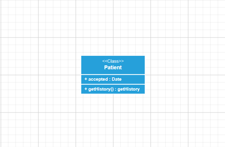
The following code example illustrates how to create a class.
let nodes = [
    {
      id: "node1",
      //Position of the node
      offsetX: 200,
      offsetY: 200,
      style: {
        fill: '#26A0DA',
      },
      shape: {
        type: "UmlClassifier",
        //Define class object
        classShape: {
          name: "Patient",
          //Define class attributes
          attributes: [{ name: "accepted", type: "Date" }],
          //Define class methods
          methods: [{ name: "getHistory", type: "getHistory" }]
        },
        classifier: "Class"
      }
     }

];
Refer to the following image.
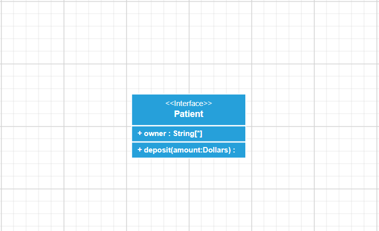
Interface
An interface is a specific type of classifier that signifies a declaration of a cohesive set of public features and obligations. Creating an interface involves defining the classifier property using the interface notation. This essential concept in object-oriented programming outlines a contract for classes to adhere to, specifying the required methods and behaviors without delving into the implementation details. Also, define the name, attributes, and methods of the interface using the interface property of the node.
The following code example illustrates how to create an interface.
let nodes = [
  {
      id: 'node1',
      //Position of the node
      offsetX: 200,
      offsetY: 200,
      style: {
        fill: '#26A0DA',
      },
      shape: {
        type: 'UmlClassifier',
        //Define interface object
        interfaceShape: {
          name: 'Patient',
          //Define interface attributes
          attributes: [{ name: 'owner', type: 'String[*]' }],
          //Define interface methods
          methods: [
            {
              name: 'deposit',
              parameters: [
                {
                  name: 'amount',
                  type: 'Dollars',
                },
              ],
            },
          ],
        },
        classifier: 'Interface',
      }
    },
 ];
Refer to the following image.
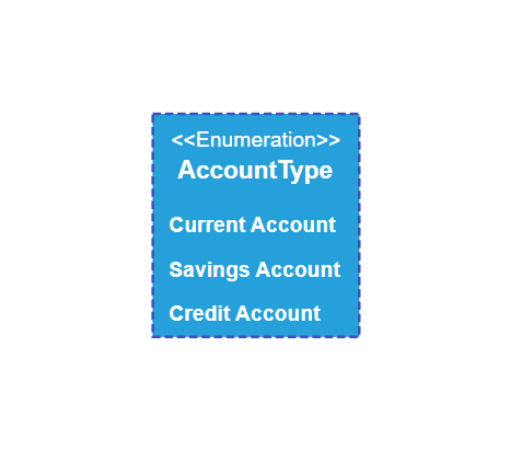
Enumeration
To establish an enumeration, designate the classifier property of the node as enumeration. Additionally, define the name and enumerate the members of the enumeration using the appropriate enumeration property of the node. This process encapsulates a set of distinct values within the enumeration, allowing for a clear representation of specific, named constants within a system. You can set a name for the enumeration members collection using the name property of the members collection.
The following code example illustrates how to create an enumeration.
let nodes = [
   {
    id: "node1",
    offsetX: 300,
    offsetY: 300,
    style: {
      fill: '#26A0DA',
    },
    shape: {
              type: 'UmlClassifier',
              enumerationShape: {
                  name: 'AccountType',
                  members: [
                      {
                          name: 'Current Account', style: {}
                      },
                      {
                          name: 'Savings Account'
                      },
                      {
                          name: 'Credit Account'
                      }
                  ]
              },
              classifier: 'Enumeration'
          },
  }
 ];
Refer to the following image.
UML class relationships
In UML class diagrams, relationships between classes illustrate how objects of different classes interact with each other. These relationships are crucial for understanding a system’s structure and behavior.
The following are the key types of UML class relationships supported by the React Diagram component:
- Association
- Aggregation
- Composition
- Inheritance (Generalization)
- Dependency
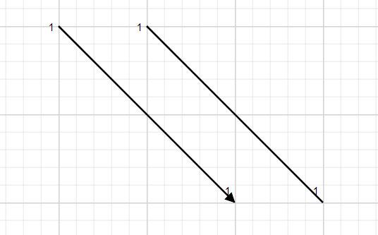
Association
An association represents a structural relationship between classes, where objects of one class are connected to objects of another class. It illustrates how instances of these two classes are linked, defining the direction of the UML connectors. The types of associations are as follows:
- Directional – Indicates a single-way direction.
- BiDirectional – Indicates a dual direction.
let connectors = [
    {
    id: 'connector1',
    //Define connector start and end points
    sourcePoint: { x: 100, y: 100 },
    targetPoint: { x: 300, y: 300 },
    type: 'Straight',
    shape: {
      type: 'UmlClassifier',
      relationship: 'Association',
      //Define the type of association
      associationType: ‘Directional’,
    },
  },
  {
    id: 'connector2',
    //Define connector start and end points
    sourcePoint: { x: 200, y: 100 },
    targetPoint: { x: 400, y: 300 },
    type: 'Straight',
    shape: {
      type: 'UmlClassifier',
      relationship: 'Association',
      associationType: 'BiDirectional',
    },
  },
 ];
Refer to the following image.
Aggregation
Aggregation is a binary association between a property and one or more composite objects that group together a set of instances. Aggregation is decorated with a hollow diamond. To create an aggregation shape, define the relationship as Aggregation.
The following code example illustrates how to create an aggregation.
let connectors = [
   {
    id: "connector",
    sourcePoint: { x: 100, y: 100 },
    targetPoint: { x: 300, y: 300 },
    type: "Straight",
    shape: {
      type: "UmlClassifier",
      relationship: "Aggregation"
    }
 ];
Refer to the following image.
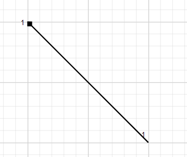
Composition
Composition is an intense form of aggregation. It is decorated with a black diamond. To create a composition shape, define the relationship property of the connector as Composition.
The following code example illustrates how to create a composition.
let connectors = [
{
    id: "connector",
    sourcePoint: { x: 100, y: 100 },
    targetPoint: { x: 300, y: 300 },
    type: "Straight",
    shape: {
      type: "UmlClassifier",
      relationship: "Composition"
    }
 ];
Refer to the following image.
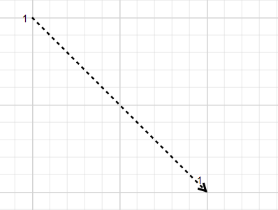
Dependency
Dependency is a directed relationship that shows that some UML elements need or depend on other model elements for specifications. It is shown as a dashed line with an opened arrow. To create a dependency, define the relationship property of the connector as a Dependency.
The following code example illustrates how to create a dependency.
let connectors = [
    {
     id: "connector",
     sourcePoint: { x: 100, y: 100 },
     targetPoint: { x: 300, y: 300 },
     type: "Straight",
     shape: {
       type: "UmlClassifier",
       relationship: "Dependency"
     }
  ];
Refer to the following image.
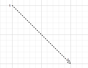
Inheritance
Inheritance is also called generalization. It is a binary taxonomic directed relationship between a more general classifier (superclass) and a more specific classifier (subclass). It is shown as a line with a hollow triangle. To create an inheritance, define the relationship as Inheritance.
The following code example illustrates how to create an inheritance.
let connectors = [
  {
     id: "connector",
     sourcePoint: { x: 100, y: 100 },
     targetPoint: { x: 300, y: 300 },
     type: "Straight",
     shape: {
       type: "UmlClassifier",
       relationship: "Inheritance"
     }
  };
];
Refer to the following image.
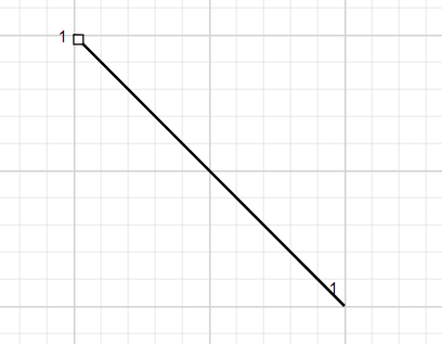
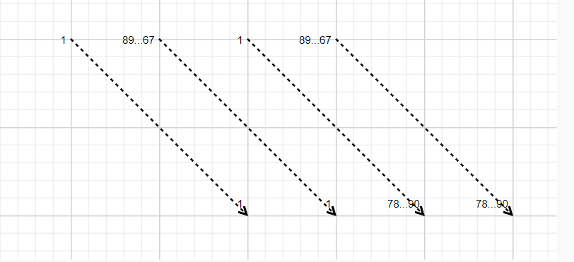
Multiplicity
Multiplicity is a definition of an inclusive interval of non-negative integers to specify the allowable number of instances of a described element. The types of multiplicity are as follows:
- OneToOne
- ManyToOne
- OneToMany
- ManyToMany
By default, the multiplicity will be considered as OneToOne. The multiplicity property in UML allows you to specify a large number of elements or a collection of elements. The shape multiplicity’s source property is used to set the source label to the connector, and the target property is used to set the target label to the connector. To set an optionality or cardinality for the connector source label, use the optional property. The lowerBounds and upperBounds could be natural constants or constant expressions evaluated to a natural (non-negative) number. The upper bound can also be specified as an asterisk (*), which denotes an unlimited number of elements. The upper bound should be greater than or equal to the lower bound.
The following code example illustrates how to customize the multiplicity.
let connectors = [
{
    id: 'connector1',
    //Define connector start and end points
    sourcePoint: { x: 100, y: 100 },
    targetPoint: { x: 300, y: 300 },
    type: 'Straight',
    shape: {
      type: 'UmlClassifier',
      relationship: 'Dependency',
      multiplicity: {
        //Set multiplicity type
        type: 'OneToOne',
      },
    },
  },
  {
    id: 'connector2',
    //Define connector start and end points
    sourcePoint: { x: 200, y: 100 },
    targetPoint: { x: 400, y: 300 },
    type: 'Straight',
    shape: {
      type: 'UmlClassifier',
      relationship: 'Dependency',
      multiplicity: {
        //Set multiplicity type
        type: 'ManyToOne',
        //Set source label to connector
        source: {
          optional: true,
          lowerBounds: '89',
          upperBounds: '67',
        },
        //Set target label to connector
        target: {
          optional: true,
          lowerBounds: '78',
          upperBounds: '90',
        },
      },
    },
  },
  {
    id: 'connector3',
    //Define connector start and end points
    sourcePoint: { x: 300, y: 100 },
    targetPoint: { x: 500, y: 300 },
    type: 'Straight',
    shape: {
      type: 'UmlClassifier',
      relationship: 'Dependency',
      multiplicity: {
        //Set multiplicity type
        type: 'OneToMany',
        //Set source label to connector
        source: {
          optional: true,
          lowerBounds: '89',
          upperBounds: '67',
        },
        //Set target label to connector
        target: {
          optional: true,
          lowerBounds: '78',
          upperBounds: '90',
        },
      },
    },
  },
  {
    id: 'connector4',
    //Define connector start and end points
    sourcePoint: { x: 400, y: 100 },
    targetPoint: { x: 600, y: 300 },
    type: 'Straight',
    shape: {
      type: 'UmlClassifier',
      relationship: 'Dependency',
      multiplicity: {
        //Set multiplicity type
        type: 'ManyToMany',
        //Set source label to connector
        source: {
          optional: true,
          lowerBounds: '89',
          upperBounds: '67',
        },
        //Set target label to connector
        target: {
          optional: true,
          lowerBounds: '78',
          upperBounds: '90',
        },
      },
    },
  },
 ];
Refer to the following image.
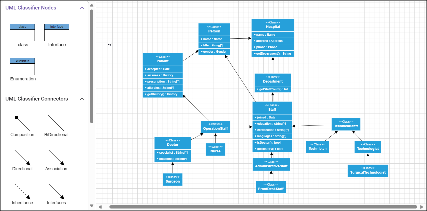
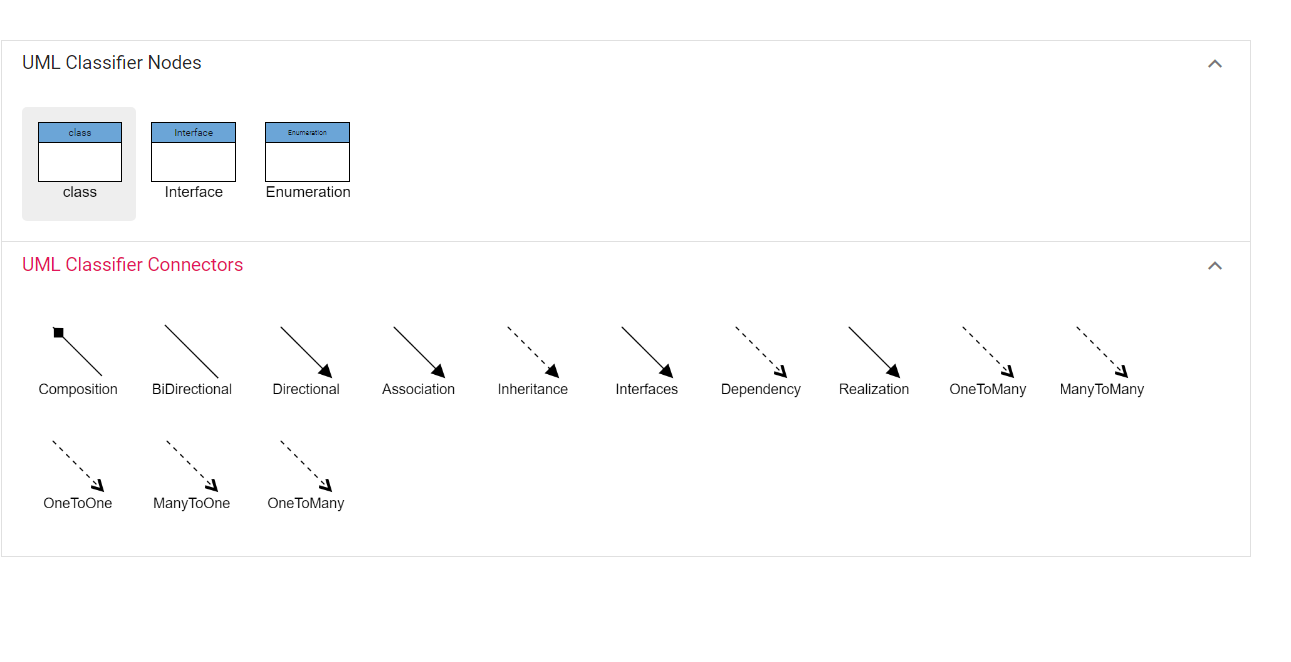
Adding UML class shapes to the React Diagram Library’s symbol palette
The React Diagram Library provides a gallery of reusable nodes and connectors called symbol palettes. It displays a collection of palettes, each showing a set of nodes and connectors. We can drag and drop them onto the diagram canvas any number of times.
UML built-in shapes can be easily rendered within a symbol palette. The symbols property of palettes is used to define UML symbols with the necessary classes and methods. This feature allows you to add a collection of predefined UML symbols to the palette, making your UML diagramming app more versatile.
Follow these steps to create a diagram symbol palette with UML class shapes.
Step #1: First, create an HTML div element that will act as the container for the diagram symbol palette.
<div id="palette-space" className="sb-mobile-palette">
  <SymbolPaletteComponent id="symbolpalette” palettes={palettes} width={"100%"} height={"700px"} />
</div>
Step #2: Initialize the diagram symbol palette by passing the required arguments, such as the width, height, and collection of symbols.
<div id="palette-space" className="sb-mobile-palette">
  <SymbolPaletteComponent id="symbolpalette" expandMode="Multiple" palettes={palettes} width={"100%"} height={"700px"} symbolHeight={90} symbolWidth={90} symbolMargin={{ left: 12, right: 12, top: 12, bottom: 12 }} />
</div>
Step #3: Now, define the collection of symbols to be included in the palette, which can be customized according to your needs. Here, we’ve added the UML class shapes and relationships.
let palettes = [
{
id: 'UmlActivity', expanded: true, title: 'UML Classifier Nodes', symbols: [
{
id: 'class',
shape: {
type: 'UmlClassifier',
classShape: {
attributes: [
{ name: 'accepted', type: 'Date', isSeparator: true },
{ name: 'sickness', type: 'History' },
{ name: 'prescription', type: 'String[*]' },
{ name: 'allergies', type: 'String[*]' }
],
methods: [{ name: 'getHistory', style: {}, parameters: [{ name: 'Date', style: {} }], type: 'History' }],
name: 'Patient'
},
classifier: 'Class'
},
},
{
id: 'Interface',
shape: {
type: 'UmlClassifier',
interfaceShape: {
name: "Bank Account",
attributes: [{
name: "owner",
type: "String[*]", style: {}
},
{
name: "balance",
type: "Dollars"
}],
methods: [{
name: "deposit", style: {},
parameters: [{
name: "amount",
type: "Dollars",
style: {}
}],
}]
},
classifier: 'Interface'
},
},
{
id: 'Enumeration',
shape: {
type: 'UmlClassifier',
enumerationShape: {
name: 'AccountType',
members: [
{
name: 'Checking Account', style: {}
},
{
name: 'Savings Account'
},
{
name: 'Credit Account'
}
]
},
classifier: 'Enumeration'
},
},
]
},
{
id: 'umlConnectorrs', expanded: true, title: 'UML Classifier Connectors', symbols: [
{
id: 'Composition',
sourcePoint: { x: 100, y: 200 },
targetPoint: { x: 200, y: 300 },
type: 'Straight',
shape: { type: 'UmlClassifier', relationship: 'Composition' }
},
{
id: 'BiDirectional',
type: 'Straight',
sourcePoint: { x: 300, y: 200 },
targetPoint: { x: 400, y: 300 },
shape: { type: 'UmlClassifier', relationship: 'Aggregation', associationType: 'BiDirectional' }
},
{
id: 'Directional',
type: 'Straight',
sourcePoint: { x: 500, y: 200 },
targetPoint: { x: 600, y: 300 },
shape: { type: 'UmlClassifier', relationship: 'Association', associationType: 'Directional' }
},
{
id: 'Association',
type: 'Straight',
sourcePoint: { x: 700, y: 200 },
targetPoint: { x: 800, y: 300 },
shape: { type: 'UmlClassifier', relationship: 'Association' }
},
{
id: 'Inheritance',
type: 'Straight',
sourcePoint: { x: 900, y: 200 },
targetPoint: { x: 1000, y: 300 },
shape: { type: 'UmlClassifier', relationship: 'Inheritance' }
},
{
id: 'Interfaces',
type: 'Straight',
sourcePoint: { x: 100, y: 400 },
targetPoint: { x: 200, y: 500 },
shape: { type: 'UmlClassifier', relationship: 'Interface' }
},
{
id: 'Dependency',
type: 'Straight',
sourcePoint: { x: 300, y: 400 },
targetPoint: { x: 400, y: 500 },
shape: { type: 'UmlClassifier', relationship: 'Dependency' }
},
{
id: 'Realization',
type: 'Straight',
sourcePoint: { x: 500, y: 400 },
targetPoint: { x: 600, y: 500 },
shape: { type: 'UmlClassifier', relationship: 'Realization' }
},
{
id: "OneToMany",
type: 'Straight',
sourcePoint: {
x: 700,
y: 400
},
targetPoint: {
x: 800,
y: 500
},
annotations: [{
margin: {
top: 10,
left: 10,
right: 10,
bottom: 20
}
}
],
shape: {
type: "UmlClassifier",
relationship: 'Dependency',
multiplicity: {
type: 'OneToMany',
source: {
optional: true,
lowerBounds: '89',
upperBounds: '67'
},
target: { optional: true, lowerBounds: '78', upperBounds: '90' }
}
}
},
{
id: "ManyToMany",
sourcePoint: {
x: 900,
y: 400
},
targetPoint: {
x: 1000,
y: 500
},
annotations: [{
margin: {
top: 10,
left: 10,
right: 10,
bottom: 20
}
}
],
shape: {
type: "UmlClassifier",
relationship: 'Dependency',
multiplicity: {
type: 'ManyToMany',
source: {
optional: true,
lowerBounds: '89',
upperBounds: '67'
},
target: { optional: true, lowerBounds: '78', upperBounds: '90' }
}
}
},
{
id: "OneToOne",
sourcePoint: { x: 100, y: 600 },
targetPoint: { x: 200, y: 700 },
annotations: [{
margin: {
top: 10,
left: 10,
right: 10,
bottom: 20
}
}
],
shape: {
type: "UmlClassifier",
relationship: 'Dependency',
multiplicity: {
type: 'OneToOne',
source: {
optional: true,
lowerBounds: '89',
upperBounds: '67'
},
target: { optional: true, lowerBounds: '78', upperBounds: '90' }
}
}
},
{
id: "ManyToOne",
sourcePoint: { x: 300, y: 600 },
targetPoint: { x: 400, y: 700 },
annotations: [{
margin: {
top: 10,
left: 10,
right: 10,
bottom: 20
}
}
],
shape: {
type: "UmlClassifier",
relationship: 'Dependency',
multiplicity: {
type: 'ManyToOne',
source: {
optional: true,
lowerBounds: '89',
upperBounds: '67'
},
target: { optional: true, lowerBounds: '78', upperBounds: '90' }
}
}
},
{
id: "OneToMany",
sourcePoint: { x: 500, y: 600 },
targetPoint: { x: 600, y: 700 },
annotations: [{
margin: {
top: 10,
left: 10,
right: 10,
bottom: 20
}
}
],
shape: {
type: "UmlClassifier",
relationship: 'Dependency',
multiplicity: {
type: 'OneToMany',
}
}
}
]
}
];Refer to the following image.
How to add a UML child at runtime?
Child elements such as members, methods, and attributes can be added to UML nodes either programmatically or interactively.
Adding UML child through code
The addChildToUmlNode method is used to dynamically add a child to a UML node during runtime, providing flexibility in modifying the diagram structure programmatically.
The following code example illustrates how to add members, methods, and attributes to the UML node at runtime.
case 'Add attribute':
        let node = diagramInstance.nameTable['Patient'];
        let attribute = { name: 'accepted', type: 'Date', style: { color: 'red' } };
       diagramInstance.addChildToUmlNode(node, attribute, 'Attribute');
      break;
      case 'Add Method':
        let node1 = diagramInstance.nameTable['Person'];
        let method = {
          name: 'getHistory',
          style: { color: 'red' },
          parameters: [{ name: 'Date', style: {} }],
          type: 'History',
        };
       diagramInstance.addChildToUmlNode(node1, method, 'Method');
       break;
Refer to the following image.
Adding UML child through user interaction
To include a child, select a node, move the mouse outside it, and position the pointer near the right side edge of the shape. A highlighter emerges between the two child elements. Click the highlighter to add a child type to the chosen UML node seamlessly.
Refer to the following image.
Loading and saving a diagram
The React Diagram control provides a useful feature that allows you to save your work and resume it later by loading the saved diagram back onto the diagram canvas.
To save your current diagram, select the Save Diagram option in the toolbar. This will save your diagram as a file on your local drive.
To load an existing diagram file, select the Open Diagram option in the toolbar. This will open the File dialog box. From there, you can browse and select the saved diagram file that you want to load.
This feature provides great flexibility and convenience, allowing you to easily pick up where you left off on a diagram or to make changes to a previously saved diagram. It is an essential feature for any diagramming app that enables users to create and manage complex diagrams.
Refer to the following GIF image.
Export the diagram
You can export the created UML Class diagram as an image file in different formats, such as JPEG, PNG, and SVG. By exporting the diagram as an image file, you can easily share it via email or other digital means or embed it in a document or presentation.
To do this, click the export button in the toolbar and select the image file format to save the UML class diagram. You can also export only the content area of the diagram by excluding the blank areas or export the entire diagram (including blank areas) based on the width and height specified in the page settings.
Refer to the following image.
Print the diagram
To print a diagram, click the Print button in the toolbar. This will open the Print dialog box, where you can select your printer and customize the print settings, such as orientation, paper size, and page margins. Then, click on the Print button to print the diagram.
Refer to the following image.
Pan and zoom
The React Diagram Library supports the following panning and zooming options:
- Pan using the scrollbars: The most straightforward way to pan a diagram is to use the scrollbars on the right side and bottom. This will allow you to scroll the diagram in the desired direction.
- Pan using the mouse wheel: You can also pan a diagram by using the mouse wheel. To scroll up or down, rotate the mouse wheel forward or backward; to scroll left or right, hold the Shift key while rotating the scroll wheel forward or backward.
- Pan using the pan tool: You can also pan a diagram by selecting the Pan tool from the toolbar. Then, hold down the left mouse button and drag the mouse to move the diagram in any direction. Refer to the following image.
- Zoom using keyboard shortcuts: The most efficient way to zoom in and out of the diagram is to use the Ctrl + mouse wheel shortcut.
- Zoom using the toolbar option: You can also zoom in or out in a diagram using the zoom dropdown in the toolbar. Refer to the following image.
Reference
For more details, refer to the creating a UML class diagram using the React Diagram Library StackBlitz demo.

Conclusion
Thanks for reading! In this blog, we’ve seen how to easily create a UML class diagram using the Syncfusion React Diagram Library. Similarly, you can create diagram creation apps like an organization chart creator, a flow chart creator, or a network diagram creator.
If you’re already a Syncfusion user, you can download the product setup from our website. Otherwise, you can download a free 30-day trial.
Please let us know in the comments section below if you have any questions. You can also contact us through our support forum, support portal, or feedback portal. We are always happy to assist you!